Creating a Marker class for StreetView panoramas
TL;DR — Get it here: source, demo, documentation.
My latest addition to the google-maps-api-addon
library is the PanoMarker, a marker which is able to remain at a
fixed position inside of a custom StreetView panorama. It can be used to
annotate points of interest (POI) inside a particular panorama regardless of the
user's viewing direction. The difficulty in creating a marker that remains at a
fixed position lies in the projection from a spherical panorama to a
two-dimensional viewport. POIs are adressed in terms of heading and pitch angles
with respect to the panorama's center. The viewport uses good old pixels for
positioning elements. In this article I will elaborate on how to find the pixel
coordinates on the viewport given heading and pitch angles of a POI.
StreetView uses an equirectangular projection for its panoramas. Here, latitudes and longitudes are evenly spread out along the image's vertical and horizontal axis, respectively. Note that along the "poles" (the image's top and bottom borders) all pixels are at exactly the same point in the projected sphere. The Google Maps API offers methods to obtain the user's point-of-view (POV) as well as the zoom factor which can be converted to a field-of-view (FOV) angle. By default, the view starts with a 90° FOV both horizontally and vertically (zoom level 1). With that, a fairly straightforward way of projecting angles to pixels comes to mind.
Linear Interpolation
We know that the viewport has a width of \(w\) pixels and our FOV is 90°, thus we have \(\frac{90°}{w}\) degrees per pixel in the horizontal axis (analog for the vertical one). Furthermore, we know that the viewport center corresponds to the POV angles (0°, 0°). With that knowledge we can calculate the difference to the POI coordinates and convert it into a pixel offset from the image center – done! Unfortunately this is too bad of an approximation in practice, resulting in a somewhat wobbly movement of the marker around the desired target (in this example the (0, 0) grid point):
We can observe that the marker is aligned perfectly if it's precisely in the center as well as the border regions. In between, the marker is drifting quite a bit from its correct position.
Circular Projection
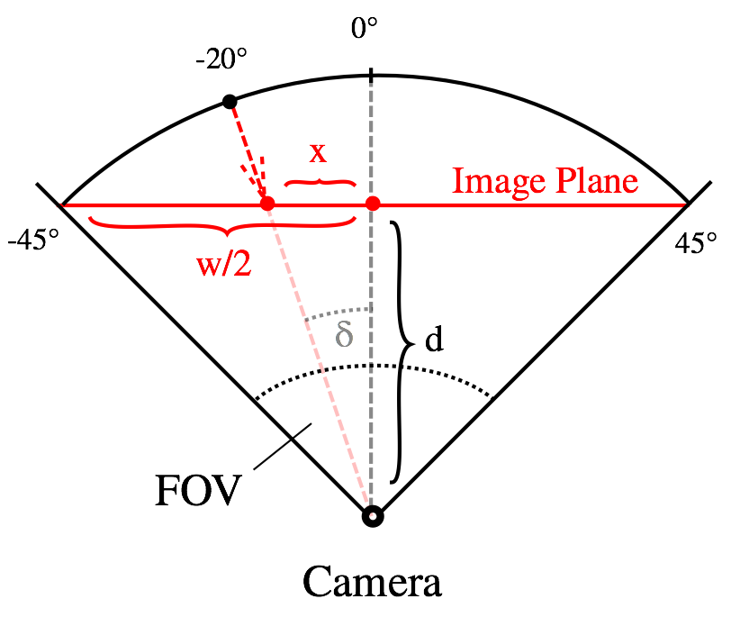
We know that we are trying to project a sphere onto a planar surface. Let's make use of that fact and do a more precise calculation. The figure on the right shows a simplified version of the problem, ignoring the pitch angle for now. Our POI has a heading of 20°. Consider the right triangle from camera (the user's POV) to the 0° and 20° points projected onto the image plane (the viewport). In this triangle, we know our desired heading \(\delta\) as well as the distance \(d\) from the camera to the plane, which can be calculated by using the bigger right triangle between camera, viewport center and viewport edge: $$ d = \frac{\frac{w}{2}}{\tan(\frac{FOV}{2})} $$
This allows us to calculate the desired pixel offset \(x = d \cdot \tan(\delta)\). Does this calculation work in practice? Kind of:
Note that the marker at (0°, 0°) is relatively stable if you turn the POV along the horizontal axis. If we consider the marker around (0°, 45°), though, the positioning is still quite bad.
Final Solution
The solution I have settled on for the Marker class is based on user3146587's fantastic post on StackOverflow. The solution performs a 3D-variant of the projection described above and works perfectly well for the whole range of pitch values:
The computation is a bit more involved. First of all, let us define the coordinate system in which we will operate. The camera will be positioned at the origin \((0, 0, 0)\). The panorma sphere is thus centered around the origin and has a diameter \(d\) (as above, the distance from camera to image plane). The panorama center with heading \(\alpha = 0°\) and pitch \(\delta = 0°\) is positioned at \((0, d, 0)\).
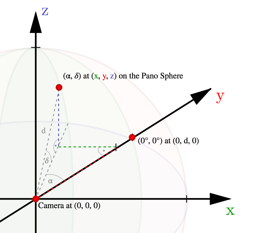
The first thing we want to do is calculate the 3D coordinates of both the viewport center and the POI in this coordinate system. So far we know the points' positions only in terms of heading and pitch angles w.r.t. to the panorama center. We will denote the POI at \((\alpha, \delta)\) with \(\mathbf{poi} = (x,y,z)\) and the viewport center at \((\alpha_0, \delta_0)\) with \(\mathbf{pov} = (x_0,y_0,z_0)\). As an example, the POI coordinates can be determined as follows: $$ \mathbf{poi} = \left( \begin{array}{c} x \\ y \\ z \end{array} \right) = \left( \begin{array}{c} d \cdot \cos(\delta) \cdot \sin(\alpha) \\ d \cdot \cos(\delta) \cdot \cos(\alpha) \\ d \cdot \sin(\delta) \end{array} \right) $$
The image plane on which we project the panorama is defined by its center at \((x_0,y_0,z_0)\) and its normal vector \((x_0,y_0,z_0)\) (i.e. in direction from camera to viewport center). Next, imagine a line going through the camera as well as our POI. To project the POI onto the image plane, we have to find the intersection point of that line with the image plane. By using the dot product between POI and POV vectors, we can determine the factor \(t\) with which the POI vector has to be scaled in order to meet the image plane (see also fig. 3): $$ t = \frac{\mathbf{pov} \cdot \mathbf{pov}}{\mathbf{poi} \cdot \mathbf{pov}} = \frac{|\mathbf{pov}|\cdot|\mathbf{pov}|}{|\mathbf{poi}|\cdot|\mathbf{pov}|\cdot\cos(\theta)} = \frac{1}{\cos(\theta)} = \frac{\text{hypotenuse}}{\text{adjacent}} = \frac{\text{target length}}{\text{original length}} $$
Having the intersection point, we can simply determine the vector from viewport center to the projected POI. However, since we're interested in 2D pixel offsets, we have to perform a basis transformation of the vector to the basis vectors of the image plane. This will give us the desired offsets \((u,v)\) in horizontal and vertical direction, which we can use directly to position our marker.
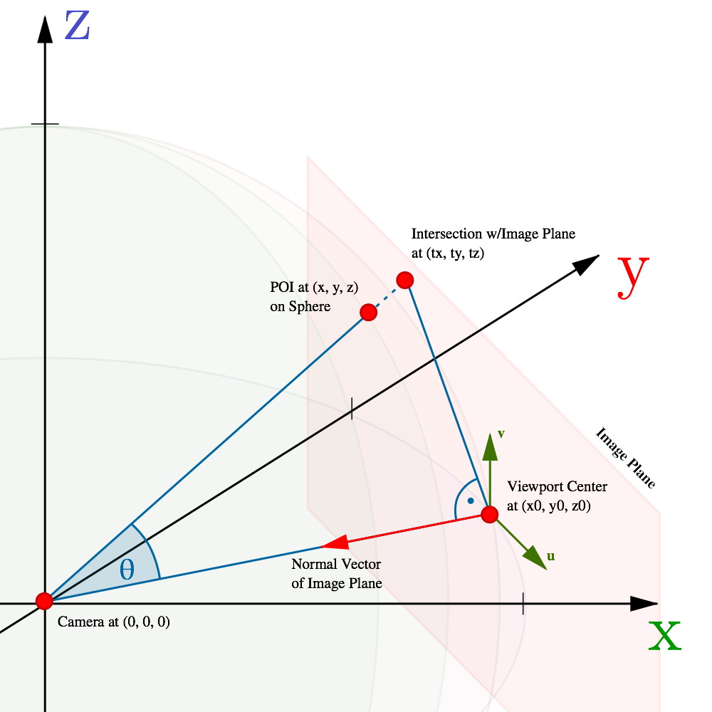
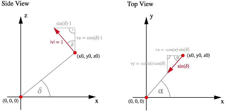
To do this, we first have to determine the orthonormal basis of the image plane. In figure 3, the basis vectors are denoted with \(u\) and \(v\). Figure 4 shows the reasoning behind the formulas for \(v\), vector \(u\) can be determined in a similar fashion. We have: $$ \mathbf{u} = \left( \begin{array}{c} \cos \alpha_0 \\ -\sin \alpha_0 \\ 0 \end{array} \right), \quad \mathbf{v} = \left( \begin{array}{c} -\sin \delta_0 \sin \alpha_0 \\ -\sin \delta_0 \cos \alpha_0 \\ \cos \delta_0 \end{array} \right) $$
Finally, we can use the dot product to project our POI vector \(t\) onto said basis vectors in order to obtain the absolute pixel offsets \(x\) and \(y\) in the direction of these vectors: $$ x = \mathbf{t} \cdot \mathbf{u} = t_x \cdot u_x + t_y \cdot u_y + t_z \cdot u_z\\ y = \mathbf{t} \cdot \mathbf{v} = t_x \cdot v_x + t_y \cdot v_y + t_z \cdot v_z $$
Other Difficulties
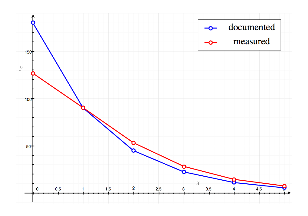
During development, I stumbled upon two weirdnesses with the Google Maps API. First of all, the FOV angles for specific zoom levels are not documented properly. In the developer's guide we can find a table listing the FOVs for zoom levels 0 to 4. Except for zoom level 1, these angles are very inaccurate, though. Figure 5 contains a comparison between the documented angles and my own measurements. This required to write a small helper method that approximated the measured values more closely. Having a correct FOV is essential for performing the projection, thus it is very important to have accurate values.
The marker extends the generic google.maps.OverlayView class in order to be
able to work inside the google maps event framework. This class will call
onAdd and onRemove callbacks when the marker is being added or removed to
the Map, respectively. These methods can be overriden by our custom marker class
in order to create or destroy the marker's DOM node and initialize its position.
Normally, these methods are being called after as soon as the view's map is
changed and the new map is in a ready state. While OverlayView.setMap()
accepts both a regular Map and a StreetViewPanorama according to the
documentation,
the previously mentioned callbacks are only fired if the given object is in fact
a google.maps.Map. In order to use an OverlayView in a StreetViewPanorama,
I had to work around that issue by polling the panorama for readiness in our
custom class and fire the callbacks appropriately. This was another issue not
immediately clear from the API reference and should probably be fixed in the
future.