A cheap IR remote for Nikon DSLRs
During a moment of boredom I decided to build an IR remote for my Nikon camera. Turned out it is a very simple and cheap project, perfect for a day with nothing else to do. The remote operates easily on distances of about 15 - 20 meters. It may be even more, but I haven't tested it yet.
Basically the remote contains a microcontroller which is powered by pressing the button. The controller then toggles an infrared LED at a frequency of about 38kHz and by that transmits the correct pattern to the camera. The remote is equivalent to Nikon's ML-L3 remote and works with a wide range of their cameras.
Hardware
The remote needs only a minimal amount of parts for construction. If you tinker with micro-controller and electronics from time to time, you will probably have most of the parts needed already available. Here is a detailed listing:
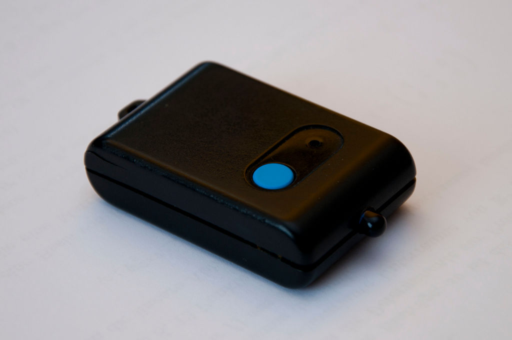
- Plastic housing for the circuit (best if it's a remote control case as in the image above)
- A piece of perf- or stripboard
- 1x Atmel ATTiny13 micro-controller
- 1x 8 MHz crystal oscillator
- 1x 3V coin cell (CR2032, preferably with soldering pins)
- 1x Push-Switch
- 1x IR-LED
- 1x about 1 or 2 ohm resistor
- 1x 100 ohm resistor
- 1x 10 kOhm resistor
- 1x BC547 NPN transistor or equivalent
- 2x 100 nF capacitors
In theory the remote should also work with the controller's internal oscillator. However, the usage of an external crystal provided better results while testing. Here are the schematics on how to connect the parts:
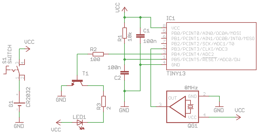
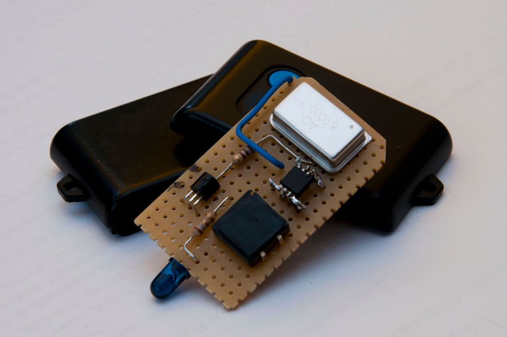
I won't provide a pcb layout, as it can vary highly depending on which plastic housing you will use. Furthermore I haven't said whether you should use SMD or DIP parts - just use those that are more convenient for you! The small amount of parts should easily fit into a housing in both cases. I myself used a mixture of both part variants, as I have used only some spare parts that I had available. Here is an inside view of the remote I have built:
Software
Before introducing the actual source code, I want to say a word or two about the protocol that the remote uses. The IR signal is modulated with a frequency of about 38.4 kilohertz. That means, when the LED is 'on', it is not constantly shining, but instead it flashes about 38400 times per second. Keeping this in mind, the LED has to shine in a specific pattern twice, with a pause of 63 milliseconds in between (I call this pattern burst in my source code). Thanks to the power of open source, you don't have to reverse engineer the pattern yourself, but someone else did this already. I took the data from BigMike's Website, where the shining pattern is described in full detail.
The source code for the micro-controller is relatively easy. As the switch is used to connect the power source to the circuit rather than as a digital input, the only thing that the micro-controller has to do after start up is to run the LED pattern, wait a bit and finally run the pattern a second time. This is reflected in the short main method:
int main(void) {
  // Initialize port
  DDRB |= (1 << IO_IR);

  burst();
  _delay_ms(63);
  burst();

  while(1) {}
}
That was easy, wasn't it? Far more interesting is the burst method:
// Clock-counts at which the LED state has to be toggled
// The values are determined by experimenting, they work
// with a 8MHz crystal oscillator
const uint16_t thresholds[8] = {2,164, 2564, 2597, 2727, 2760, 3054, 3087};

// Sends a single data burst (two of them are needed)
void burst() {
  uint16_t clock = 0;
  uint8_t current_threshold = 0;
  uint8_t status = 0;

  while(clock++ < BURST_LENGTH) {
    if (clock == thresholds[current_threshold]) {
      status ^= 1;
      current_threshold++;
    }

    if (clock & status) {
      LED_ON();
    } else {
      LED_OFF();
    }

    _delay_us(CLOCK_DURATION);
  }

  LED_OFF();
  return;
}
Now, what is happening here? Basically, one while-loop takes roughly thirteen microseconds in order to achieve the modulation frequency of 38.4 kHz. During each iteration, a counter is incremented by one. It represents the count of clocks (at modulation frequency - not processor clocks) that have passed since beginning of the burst. This counter is matched against an array of threshold values. When the counter reaches one of these thresholds, the LED state will be toggled from "on" to "off" or the other way around.
After checking for a matching threshold, it is checked whether the LED should shine or not. It should only shine when two conditions are met:
- We have an odd clock-count (this ensures that the LED will shine only every other clock and not constantly)
- The status is set to "on"
Despite the fact that the status field is an 8-bit integer, I use only the least significant bit to indicate whether the LED is supposed to be "on" or "off". The clock count is incremented after every loop, that means the least significant bit toggles between one and zero every iteration (as the count toggles between odd and even respectively). This allows us to use a bitwise AND-operation to connect these two fields. When the resulting value is anything other than zero, both criteria are met and the LED will be actually turned on.
With this method, we have everything that we need for a working remote. I hope this article gives you enough information on how to build your own Nikon IR remote. If you have any questions, feel free to send me an e-mail!